Wide field three colours simultaneous imager (as of 2014/7/14)
Basic info.
| Environment |
|---|
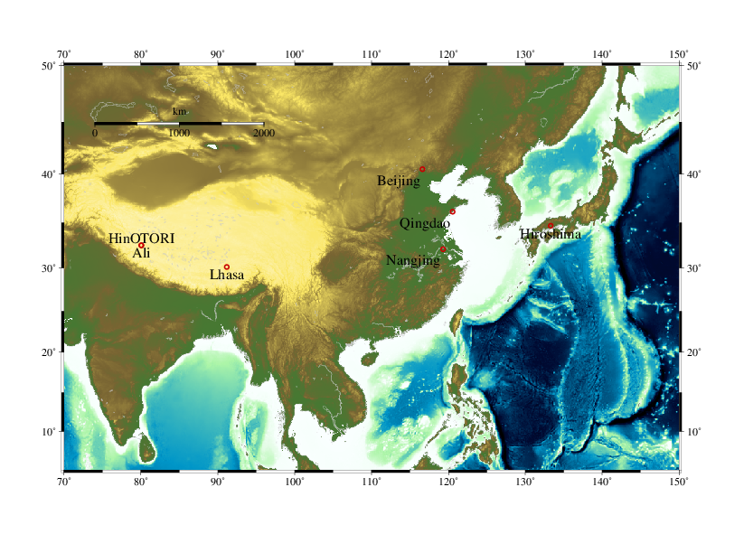
| Latitude | 32.31373N |
| Longitude | 80.030018E |
| Altitude | 5130m |
| Telescope |
|---|
| Type of telescope | Pure Ritchey-Chretien system |
| Diameter of the primary relection mirror | 510mm |
| F-ratio of the primary relection mirror | 3 |
| Coating the primary relection mirror | Al with the SiO protection layer |
| Total focal length | 4080mm |
| Backfocus | 460mm |
| Usable backfocus from backflange | 360mm |
| Instrument |
|---|
| Field of view | 24 x 24 arcmin2 |
| Pixel size | 13.5um |
| Available bands | SDSS-u, Rc, Ic |
| Optical elements | Fused silica |
| Focal length with corrector | 4250mm |
| Pixel scale | 0.68mm |
| Mount |
|---|
| Tracking accuracy | 0.3arcsec rms w/ open loop (expected) |
| Pointing accuracy | < 3arcmin |
| Maximum slweing speed | 2 degrees/sec |
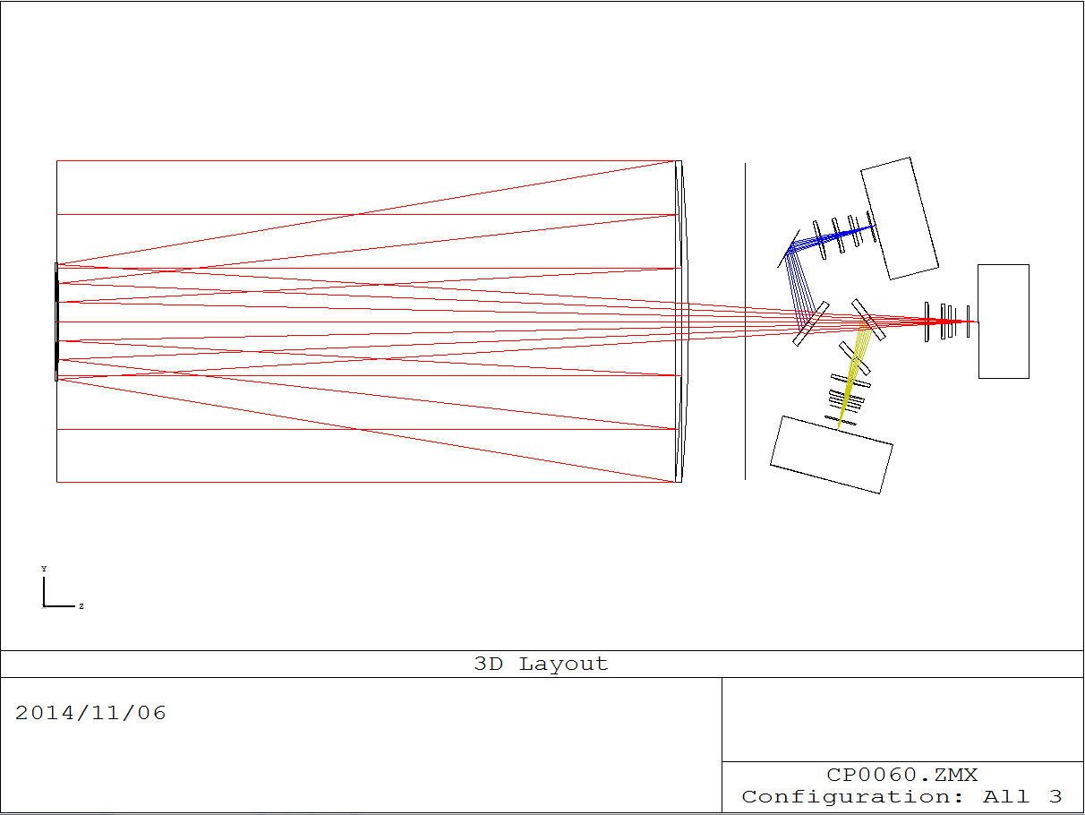
Optical layout
We adopt Ritchey-Chretien system to eliminate spheriacal and coma abberations. Introducing two spherical same material corrector lens system, we can obtain fine image quality up to 0.5 degree of field of view (
Wynne 1968).
We divide the telescope beam into three channels with dichroic mirros.
Key ideas
- A unique capability of u-band for this kind of instruments. Picking up first, using fused-silica and using the blue enhanced CCD
- Place corrector lens system after dichroic mirrors rather than adopting common corrector in order to make anti-reflection coating easily optimizing for each channel
- A wedged compensator glass against to the astigmatic abberation induced by the dichroic mirror for the Rc-band channel (green)
- 2 times less pixel size than MITSuME to obtain finer image
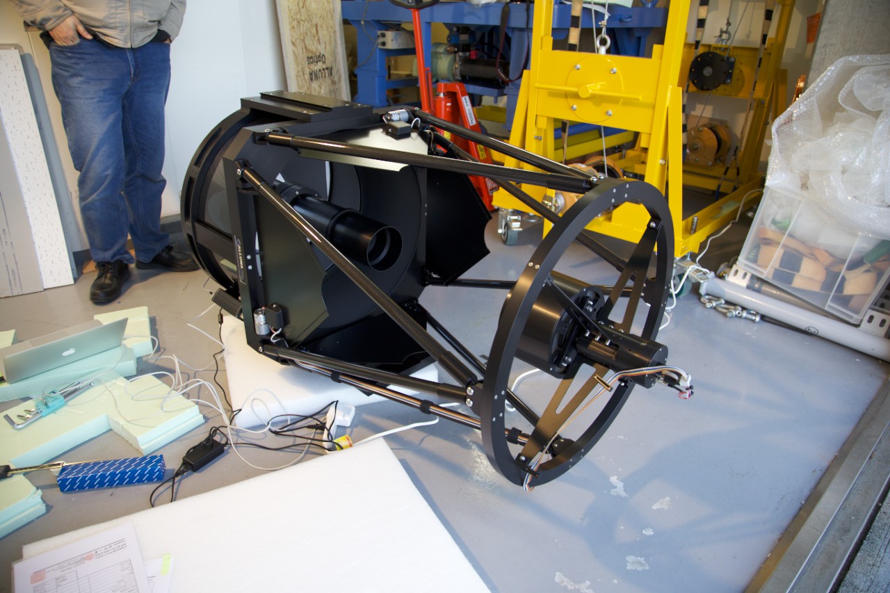
Telescope
Filters
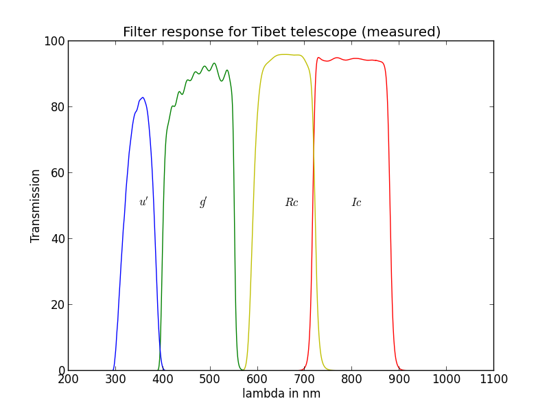
| band | mean wavelength in nm | 10% trasnmission wavelength (min) | 10% trasnmission wavelength (max) | Compositions |
|---|
| u' | 348.7 | 301.3 | 391.7 | KG3(2mm) + UG11(1mm) + Fused Silica (2mm) |
| Rc | 656.4 | 580.3 | 729.9 | OG590(3mm) + Fused silica(2mm) |
| Ic | 798.0 | 709.3 | 887.7 | R-60(5mm) HOYA colored glass |
Dichroic mirros
- Simultaneous imaging system requires beam splitters such as dichroic mirror with accurate surface. Dichroic mirror coating sometimes introduces ``bend'' on the bank glass, which might loose optical performance. We take care of this bend with making the bank glass thicker.
- However, a thicker glass will introduce optical aberration. A thiner glass is also important for the image.
Measured surface (provided by
Asahi Spectra)
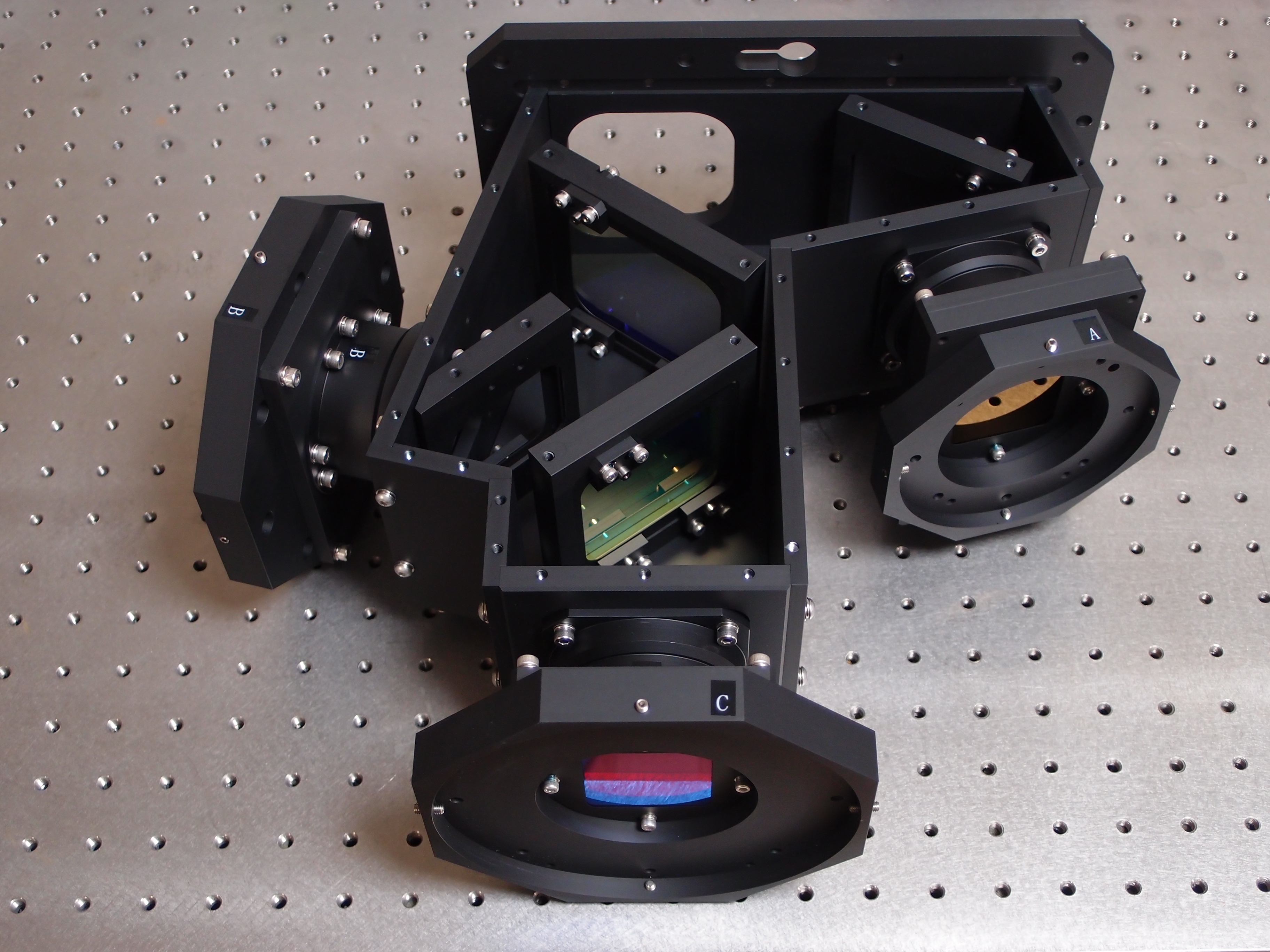
Corrector lens system and its housing
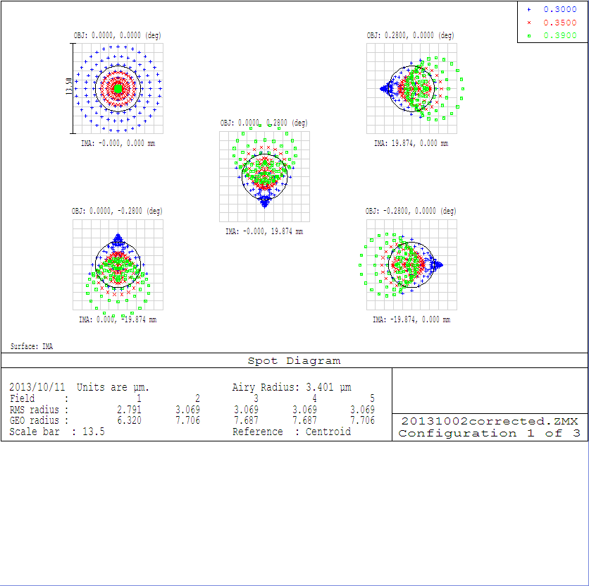
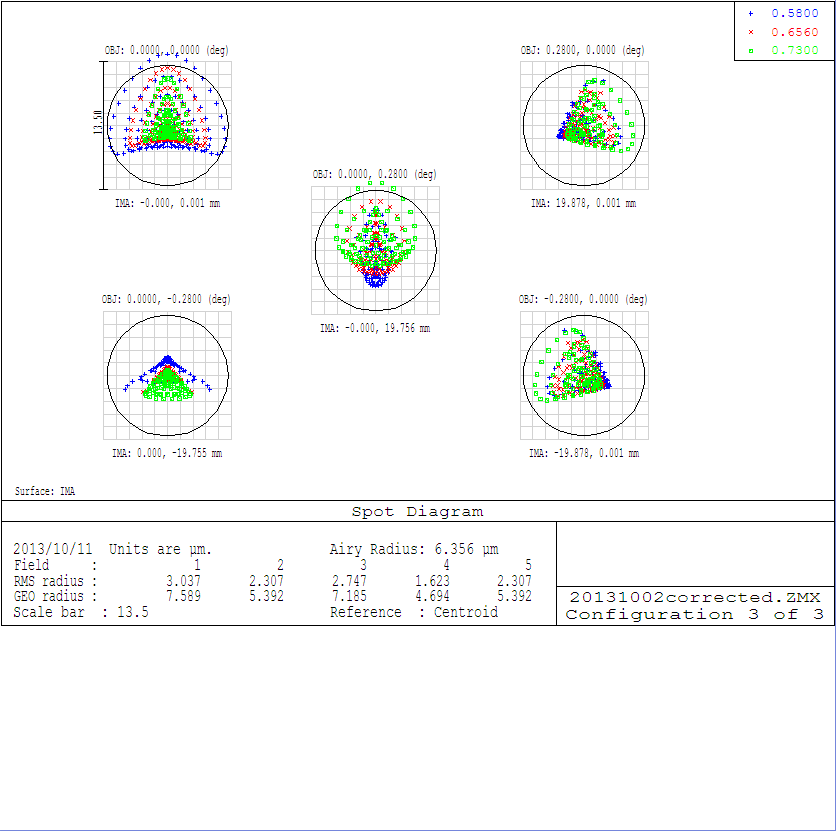
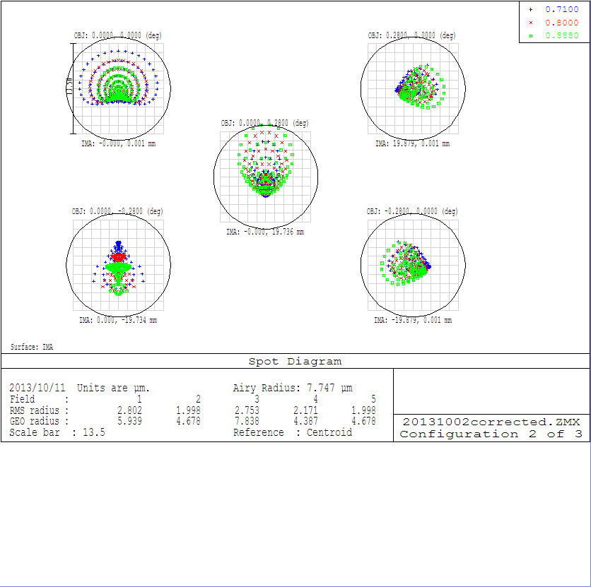
Expected spot diagram
Boxes in each figure are identical to the pixel size. All of the rms radii fit within the pixel size.
u-band channel
Rc-band channel
Ic-band channel
Detectors
u-band channel
- Apogee Alta U42-UV / D02F-MG43D-U04240-UV1F / E2VCCD42-40 (UV)
Rc and Ic-band channel
- Apogee Alta U42 / D09F-MG63D-U04240-MB0F / E2VCCD42-40 (Midband)
Dewar window consists of double Fused Sillica with MgF2. A thickness of each is 1mm.
System Diagram
Tracking System
see
Activity report
Atmosphere
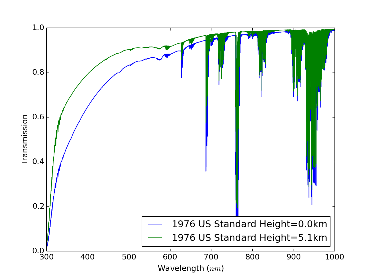
The atmospheric model is "1976 US Standard Asmosphere" with airmass = 1.2, H2O PWV=1.5mm. This atmospheric model was calculated by Prof. Yasuda (Kavli IPMU) using MODTRAN.
Total performance
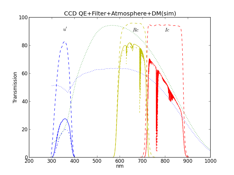
The lines show the trasmission at the 5100m altitude, the dashed lines show at the filter only and the dashed dotted lines show that at the ground.
In this figure, the CCD quantum efficiency (dotted line, blue for uv-enhanced and green for mid-band, -70C) and the dichroic mirros reflection and transmission (not shown here) are included in the resulting curve for 5100 and 0m.
| band | mean wavelength in nm | Gain |
|---|
| u' | 359.7 | 1.43 |
| Rc | 653.0 | 1.03 |
| Ic | 790.7 | 1.03 |
``Gain'' is a ratio of integrated transmission curves between 0m and 5100m convolving with the CCD quantum efficiency, Filter transmission, Atmosphere and properties of the dichroic mirros while ``wavelength'' is derived by the filter.
For u-band, the UV-enhanced CCD at the 5100m site gains 3.01 times higher efficiency thant the mid-band CCD at the ground.
Softwares
Here is links to softwares related to this projects. These are still developing.